Ge Wall Switch Timer Instructions

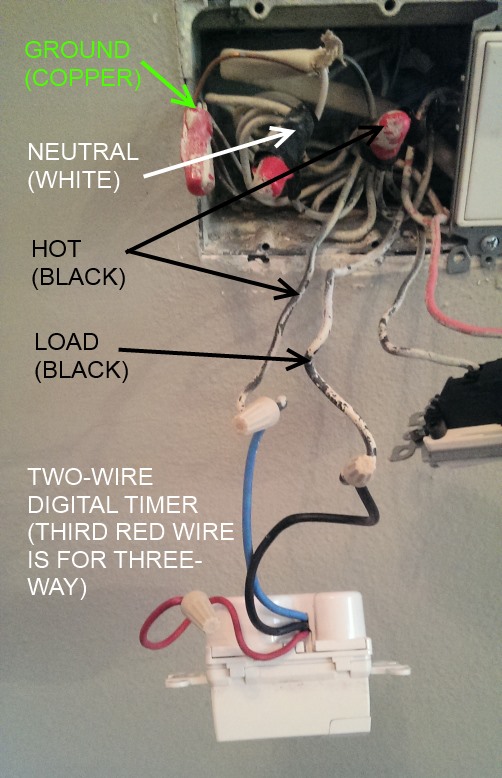
Timer For 3 Way Switch
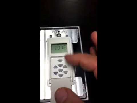
How To Program A Smart Digital Timer Youtube

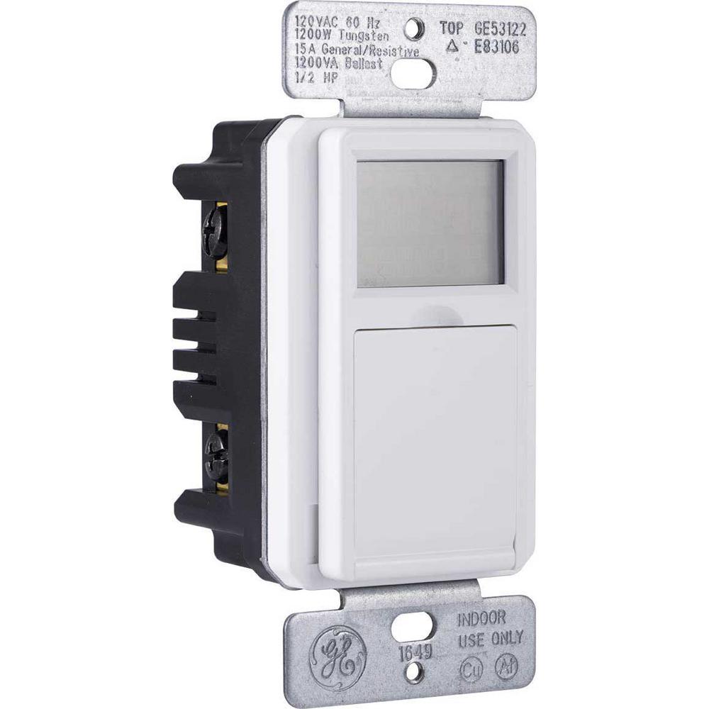
Ge 24 Hour Indoor In Wall Mechanical Timer White
Ge 7 Day Programmable Indoor Outdoor In Wall Digital Timer 32787 The Home Depot

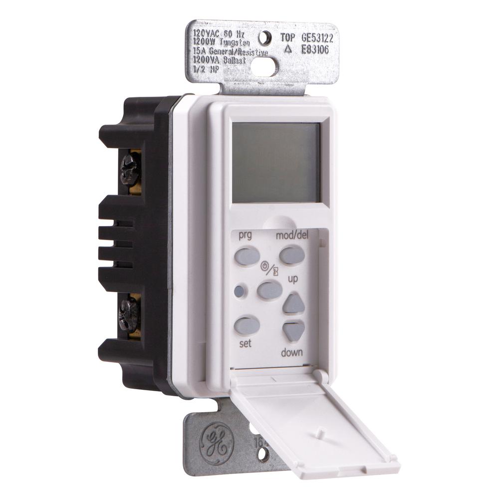
Ge 15312 Timers Download Instruction Manual Pdf

Ge Timers And Manuals
Timer door also doubles as a convenient on off push button overrides timer.
Ge wall switch timer instructions.

Ge 15 Amp White Direct Wire Digital Timer At Menards

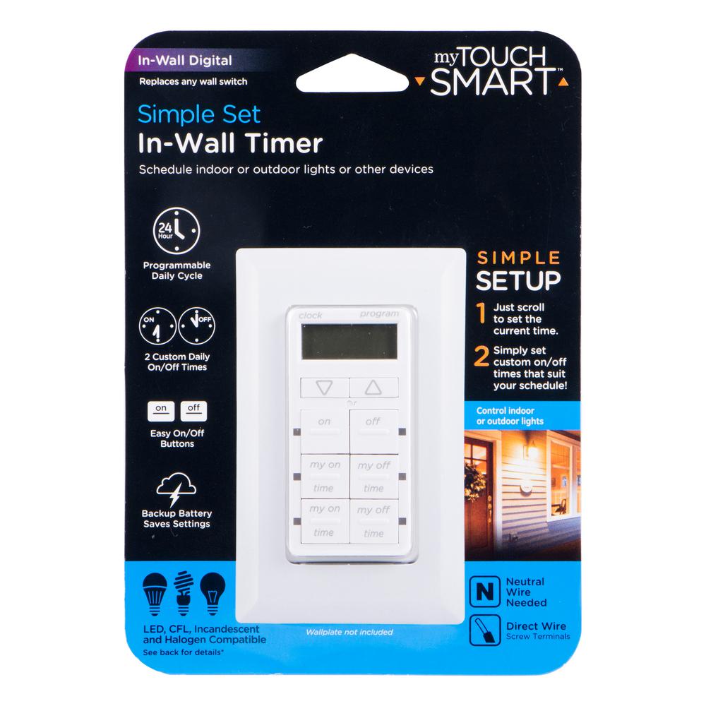
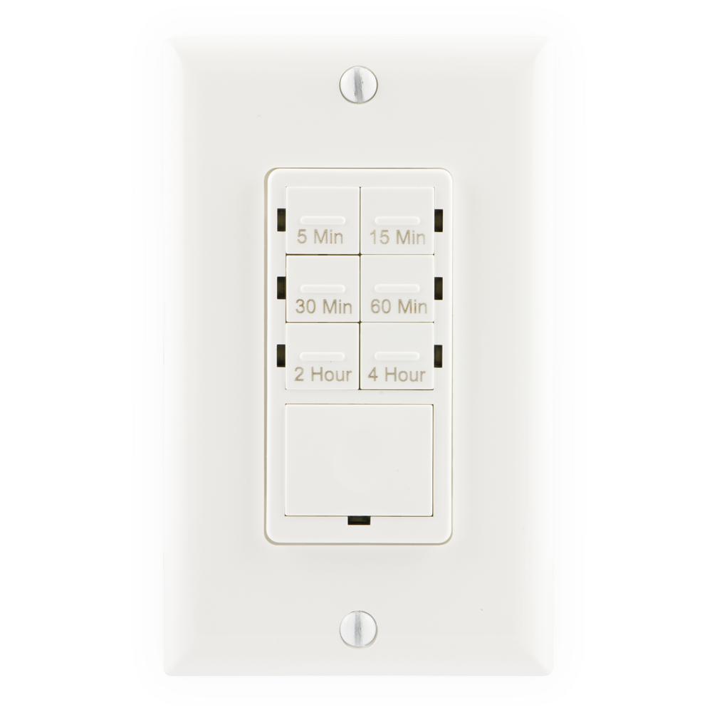
Ge 25055 Touchsmart In Wall Digital Timer With 6 Pushbuttons White Amazon Com

Ge 13869 Smart Light Switches Dimmers Download Instruction Manual Pdf
How To Choose And Install A Programmable Wall Switch Timer The Frugal Noodle

Upm Timers And Manuals

Ge Z Wave Plus Dimmer Wall Toggle Smart Switch Gen5 Ge Smart Switch Wiring Diagram Cliparts Cartoons Jing Fm

Ge 7 Day Indoor In Wall Sunsmart Digital Timer White

Ge Enbrighten Z Wave Plus Smart Switch With Quickfit And Simplewire White
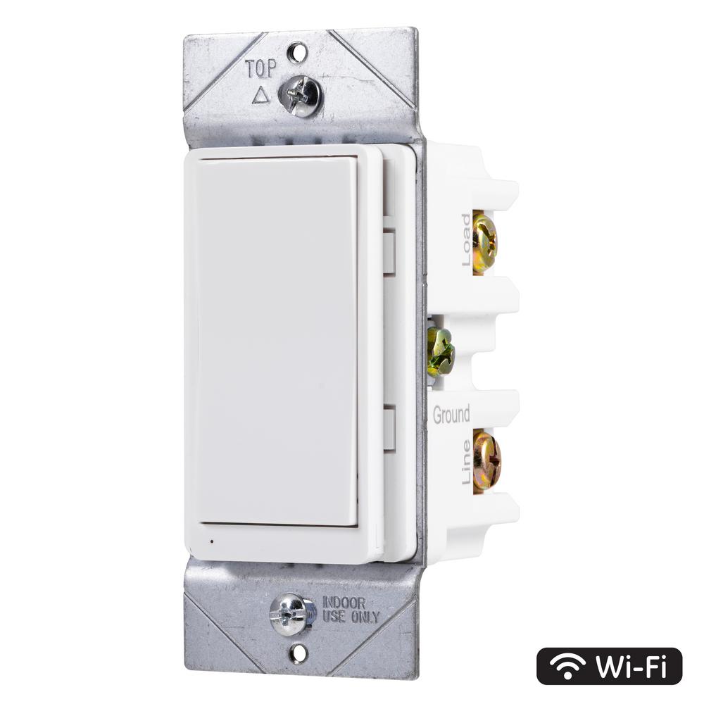
Ge In Wall Wi Fi Smart Switch White 40792 The Home Depot

Ge Auto Shut Off Timer Switch 15 Amp 1 2 Hp Lights Fans Etc

General Electric Indoor Mechanical Timer 24hr With 1 Outlet Target

Ge 15069 Automatic Shut Off 60 Minute Timer Switch Single Pole White Electrical Timers Amazon Com
Ge In Wall 15086 Ge Smart Digital Timer Manuals
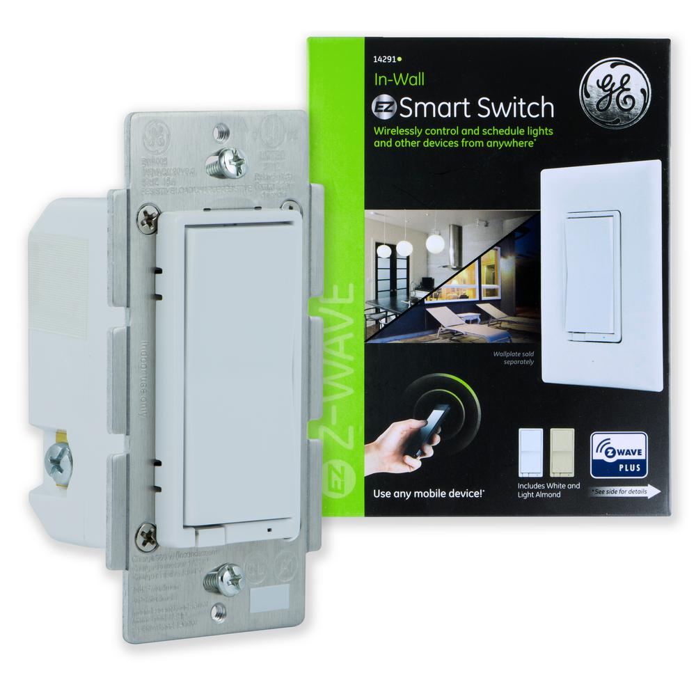
Ge Z Wave Plus In Wall Smart Switch 14291 The Home Depot
Tork 5 Minute To 4 Hour Indoor In Wall Countdown Digital Lighting And Appliance Timer White R5m4hw The Home Depot
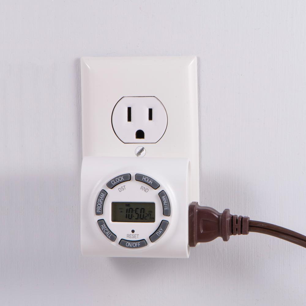
Ge 7 Day Indoor Programmable Plug In Digital Timer 15089 The Home Depot

Ge In Wall Mechanical Countdown Timer Switch Spring Wound Up To 60 Minutes No Neutral Wire Needed Ideal For Lights Exhaust Fans And Heaters Led 15305 Wall Timer Switches Amazon Com
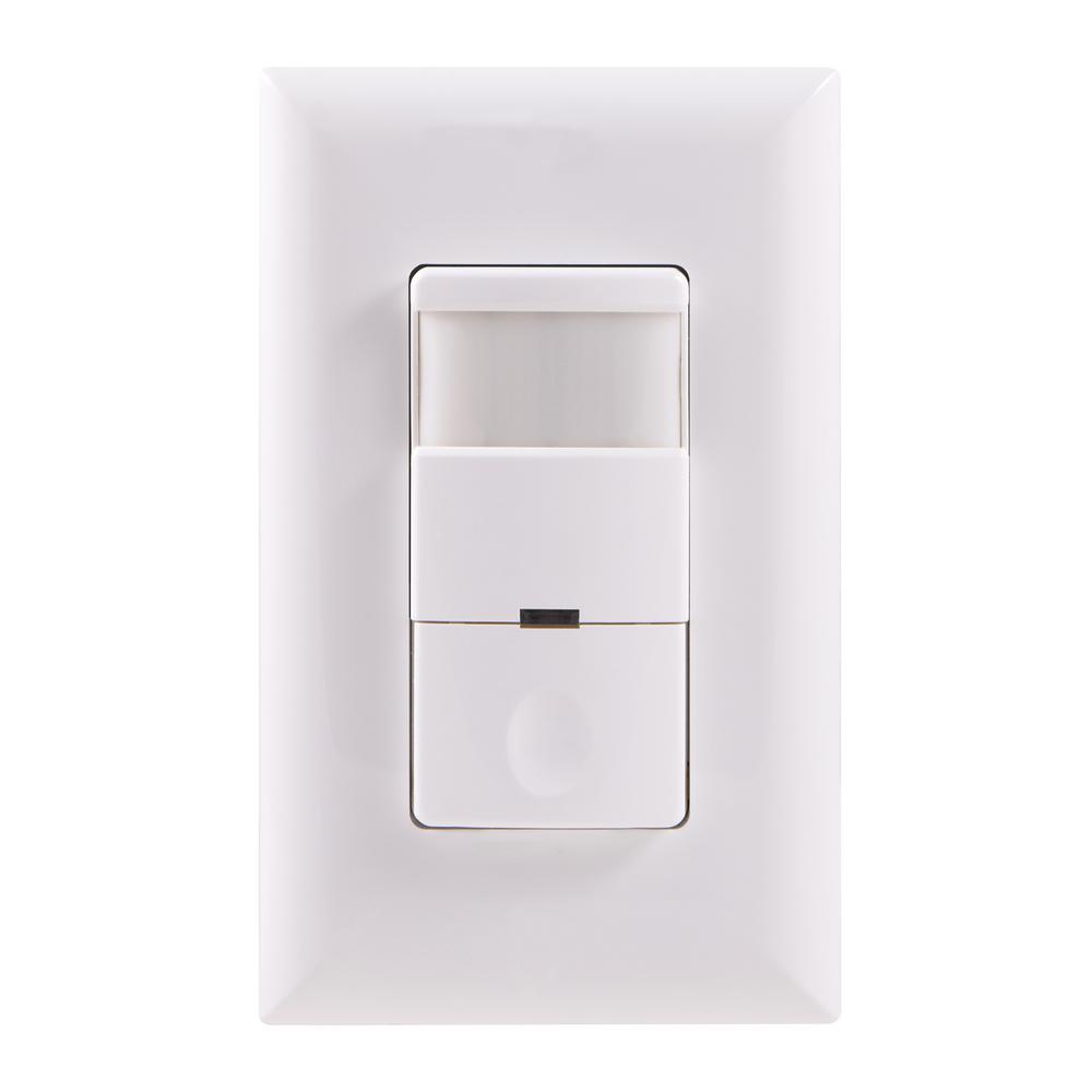
Ge Motion Sensing Switch With Automatic Shut Off Feature White 11927 The Home Depot
Https Encrypted Tbn0 Gstatic Com Images Q Tbn 3aand9gcqlk8gqlqdyavw1aouukuugfxelholpxltgn0ai O0 Usqp Cau

Ge Z Wave Plus In Wall Smart Switch Toggle White
Defiant 15 Amp In Wall 3 Way Daylight Adjusting Digital Timer Switch With Screw Terminals White 32648 The Home Depot

Ge Ultrapro In Wall Motion Sensing Switch With Occupancy And Vacancy Options Single Pole Automatic Manual Controls 150 Degree 30ft Detection Zone Custom Timer Indoor 11927 White Amazon Com

Ge 24 Hour Indoor Basic Mechanical Timer 2 Pack Plug In Daily On Off Cycle 30 Minute Intervals For Lamps Seasonal Appliances And Portable Fans 15417 Polarized 1 Outlet Black White Mechanical Plug In Timer

Ge Mytouchsmart In Wall Wifi Smart Outlet White
Source : pinterest.com
